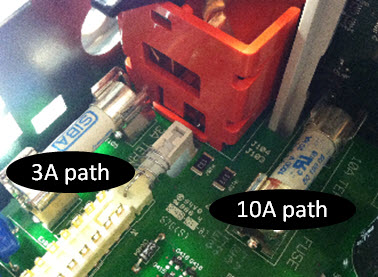
This section describes the procedure for testing and replacing the 3 A and 10 A current path fuses inside the instrument.
|
Only qualified, service-trained personnel who are aware of the hazards involved should remove instrument covers. Always disconnect the power cable and any external circuits before removing the instrument cover. Some circuits are active and have power applied even when the power switch is turned off. Always disconnect all inputs, cords, and cables before disassembling the instrument. |
|
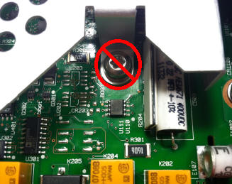
Do not turn the screw that fastens the shield in place, as this will affect the instrument's calibration.
|
To determine whether the instrument's 3 A current path has a fuse that must be replaced, press [Cont] to put the DMM in continuity measurement mode, and short the HI Input terminal to the 3 A current terminal. If the measurement displays OPEN, one of the two fuses must be replaced. One fuse is accessible from the instrument's rear panel; the other is internal.
If the 3 A current path has a bad fuse, it is very likely to be the fuse accessible from the lower left corner of the instrument's rear panel (part number 2110-1547, 3.15 A, 500 VAC/400 VDC, time delay). Simply use a flat-blade screw driver to turn the fuse holder counter-clockwise and access the fuse. Put the new fuse into the fuse holder and insert the assembly back into the instrument, turning the fuse holder clockwise to lock it in place.
If the 3 A path still has a bad fuse, replace the internal 3 A current path fuse as described below.
To determine whether the instrument's 10 A current path has a fuse that must be replaced, press [Cont] to put the DMM in continuity measurement mode, and short the HI Input terminal to the 10 A current terminal. If the measurement displays OPEN, replace the internal 10 A current path fuse as described below.
Both internal current path fuses are part number 2110-1402, 11 A, 1000 V, fast acting. To replace an internal fuse:
This concludes the fuse replacement procedure.